The Critical Role of PCB Reliability in Modern UAV Missions
Military UAVs operate in environments that push electronics to their breaking point. From high-altitude reconnaissance to electronic warfare in dense EMI environments, the onboard PCB acts as the neural system integrating propulsion, navigation, and encrypted communication. In a mission-critical context, a single signal disruption can lead to catastrophic failure.
To ensure zero-failure tolerance, UAV PCBs must withstand:
- Thermal Extremes: Rapid cycling between high-current heat and sub-zero altitudes.
- Mechanical Stress: Intense launch acceleration and high-frequency rotor vibration.
- EMI Challenges: Hostile jamming and complex co-located RF interference.
- Environmental Hazards: Salt spray, humidity, and high-altitude condensation.
Since 1989, PCE PCB has specialized in Taiwan-based precision manufacturing. With ISO 9001 and UL certifications, we provide the localized security and stringent quality benchmarks required for the next generation of defense-grade UAVs.
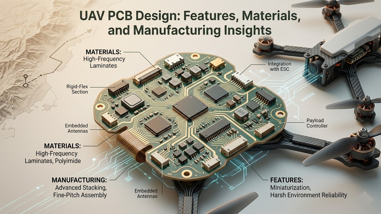
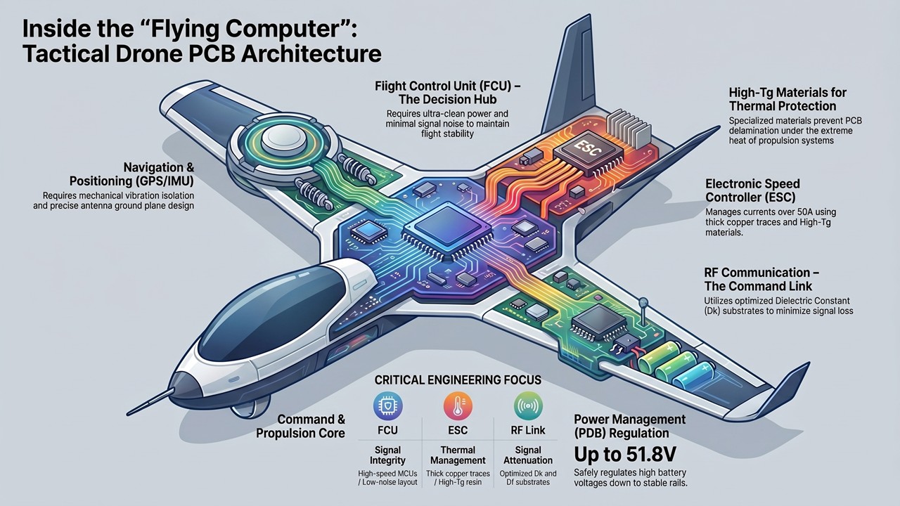
1. Core Components: The Architecture of Tactical Drone Electronics
A military UAV is a high-performance flying computer. Its PCB must seamlessly integrate diverse subsystems, each requiring specific design strategies:
- Flight Control Unit (FCU) – The Decision Hub: Powered by high-speed MCUs, the FCU requires ultra-clean power delivery and minimal signal noise. Any layout flaw here directly impacts flight stability.
- Electronic Speed Controller (ESC) – Power & Propulsion: Handling currents often exceeding 50A, these areas demand thick copper traces, robust thermal vias, and High-Tg materials to prevent delamination under extreme heat.
- Navigation & Positioning (GPS/IMU): These are highly sensitive to interference. GPS requires precise antenna ground plane design, while the IMU requires specialized layout placement to isolate it from mechanical vibrations.
- RF Communication – The Command Link: Operating across encrypted tactical bands, these modules are acutely sensitive to the PCB substrate. We utilize materials with optimized Dk (Dielectric Constant) and Df (Loss Tangent) to minimize signal attenuation.
- Power Management (PDB): Responsible for regulating battery voltages (up to 51.8V) down to stable 3.3V/5V rails. Strategic decoupling capacitor placement is critical to prevent voltage transients from resetting the system.
2. Mastering SWaP: Size, Weight, and Power Optimization
In UAV engineering, SWaP is the governing constraint. Every gram saved translates to more payload or longer flight endurance.
At PCE PCB, we address these constraints through advanced manufacturing:
- Size: Maximizing Density
We shrink the electronics footprint without sacrificing performance through:
- HDI & Microvias: Laser-drilled microvias recover routing channels, allowing for significantly smaller board outlines.
- Blind/Buried Vias: Complex stack-ups that free up surface area for high-density component placement.
- Component Co-location: Strategic grouping to minimize trace lengths and parasitic interference.
- Weight: Eliminating the "Wire Tax"
Weight reduction is achieved by rethinking connectivity:
- Rigid-Flex Integration: Replacing bulky wire harnesses and connectors with integrated Rigid-Flex solutions can reduce interconnect weight by 20% to 40%.
- FPC Implementation: Utilizing thin, flexible circuits to navigate tight spaces while removing heavy mechanical mounting hardware.
- Power: Efficiency via Thermal & Layout Design
Every wasted milliwatt is flight time stolen from the mission. We optimize power through:
- Heavy Copper Pours: Using 2oz to 4oz copper for ESC and PDB paths to minimize resistive losses and voltage drops.
- Thermal Via Arrays: Strategic heat dissipation through inner copper planes, reducing component junction temperatures.
- Domain Isolation: Physical separation of high-current power stages from sensitive RF/Analog circuits to eliminate switching noise.
3. Diverse PCB Types for Tactical UAV Requirements
No single PCB type serves every function within a military UAV. The avionics architecture demands a portfolio of board technologies, each selected to match the specific electrical, mechanical, and spatial requirements of its subsystem.
| PCB Type |
Primary UAV Application |
Advantages |
|
Single / Double-Sided PCB
|
Simple sensor interfaces, basic power distribution in auxiliary modules
|
Low cost; fast turnaround for non-critical subsystems
|
|
Multilayer PCB (4–20+ layers)
|
Flight control main boards, communication processing boards
|
Dedicated ground planes for EMI suppression; high routing density for complex signal architectures
|
|
HDI PCB (High-Density Interconnect)
|
AI inference modules, high-speed image processing SoCs
|
Microvias enable BGA fanout in minimal board area; supports advanced layer stack-up for high-speed signals
|
|
FPC (Flexible PCB)
|
Camera gimbal signal routing, antenna interconnects, foldable airframe connections
|
Eliminates connectors; reduces weight; enables 3D routing through complex airframe geometries
|
|
Rigid-Flex PCB
|
Foldable wing structures, vibration-isolated sensor mounts, 3D avionics packaging
|
Combines structural rigidity with flexible interconnect; replaces multiple connector pairs with a single integrated assembly
|
PCE PCB manufactures the full spectrum of these board types, from standard multilayer rigid boards through to complex multi-bend rigid-flex assemblies, providing UAV designers with a single qualified source for their entire avionics PCB portfolio.
4. Advanced Design: Rigid-Flex & FPC Integration (The PCE PCB Advantage)
At PCE PCB, Rigid-Flex and FPC technologies are our core strengths. For military UAVs, these aren't just "options"—they are transformative solutions for reliability and space optimization.
- Eliminating Failures: Replacing Wire Harnesses
Connectors are often the weakest link in an airframe. Rigid-Flex PCBs eliminate these failure points by integrating interconnects directly into the board stack-up, offering:
- Enhanced Reliability: Fewer mechanical connectors mean fewer points of failure under vibration.
- 3D Design Freedom: Navigate tight airframe structures and fold lines that rigid boards cannot reach.
- Signal Integrity: FPC traces provide superior impedance stability compared to discrete wire harnesses.
- Solving High-Level Manufacturing Challenges
Rigid-Flex production is notoriously difficult. Here is how we ensure IPC Class 3 reliability:
- CTE Mismatch Control: We use precision pre-shrinkage compensation and modified resin layers to prevent delamination between FR-4 and Polyimide (PI) layers.
- Via Complexity: Our facility specializes in blind and Buried Vias, maintaining strict hole-wall copper thickness even in high-density, constrained board outlines.
- Bend Stress Management: During our DFM review, we calculate bend radius geometry and stiffener placement to prevent copper fatigue from high-cycle drone vibrations.
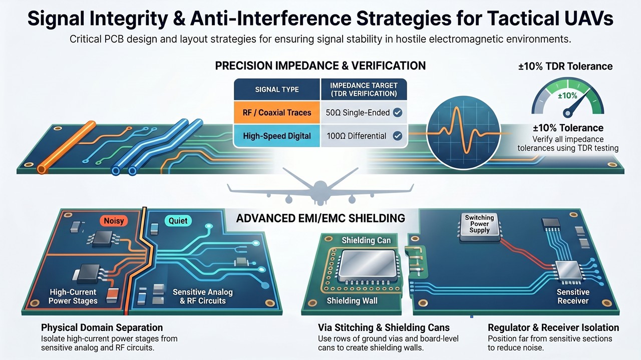
5. Signal Integrity & Anti-Interference Strategies
In a tactical UAV, the internal electromagnetic environment is often hostile. High-current motor drivers and RF transmitters generate significant noise. Without disciplined PCB design, signal integrity will degrade, leading to mission failure.
Precision Impedance Matching
- 50Ω Single-Ended: For RF and coaxial-equivalent traces.
- 100Ω Differential: For high-speed digital pairs.
- TDR Verification: We verify impedance tolerances to ±10% using Time Domain Reflectometry (TDR) testing.
Advanced EMI/EMC Shielding
- Continuous Ground Planes: Providing a low-impedance return path to eliminate ground loops.
- Domain Separation: Physically isolating high-current power stages from sensitive analog and RF circuits.
- Via Stitching: Creating "shielding walls" with ground via rows to prevent coupling between functional zones.
Frequency Band Isolation (GPS & Video)
- Unbroken Reference Layers: Routing GPS traces over dedicated, noise-free ground layers.
- RF Shielding Cans: Utilizing board-level shielding where layout isolation alone is insufficient.
- Regulator Isolation: Keeping switching power supplies far removed from sensitive receiver sections.
6. Strategic Material Selection: Defining the Performance Ceiling
A UAV’s mission capability is only as good as the substrate it’s built on. PCE PCB maintains strategic partnerships with global material leaders to ensure the optimal balance of signal integrity, thermal stability, and weight.
High-Frequency Systems: Low Dk / Low Df Materials
- Brands: Rogers, Isola, Arlon, TUC.
- Application: GPS, Satellite links, and Electronic Warfare (EW).
- Why it Matters: At GHz frequencies, standard FR-4 causes significant signal attenuation. By using substrates with Df values as low as 0.001, we dramatically extend the effective communication range of your RF systems.
High-Power Propulsion: High-Tg and Thick Copper
- Brands: Nanya, EMC (Elite Material).
- Application: ESCs and Power Distribution Boards (PDB).
- Why it Matters: High-current motors generate intense heat. We specify High-Tg FR-4 (Tg ≥ 170°C) combined with 2oz–4oz thick copper to prevent board delamination and maximize current-carrying capacity.
Flexible Interconnects: Polyimide (PI)
- Application: Foldable airframes, gimbal cables, and antenna flex.
- Why it Matters: Polyimide sustains temperatures over 200°C and survives thousands of bend cycles—essential for the 3D routing required in compact drone airframes.
| Material Type |
Benefit |
Ideal Application |
|
Metal Core (MCPCB)
|
Maximum thermal dissipation; conducts heat orders of magnitude faster than FR-4.
|
High-power ESCs & LED drivers
|
|
Halogen-Free
|
Superior chemical/moisture resistance; stable in salt spray environments.
|
Maritime & High-humidity missions
|
|
PTFE / Composites
|
Ultra-low loss at frequencies above 10 GHz.
|
mmWave Radar & Next-gen EW
|
7. Mechanical Durability: Surviving High-G and Environmental Stress
A tactical UAV PCB must survive the shock of launch, sustained rotor vibration, and rapid altitude transitions. At PCE PCB, we integrate mechanical durability into the fabrication process from day one.
Combating Solder Joint Fatigue
High-G maneuvers and constant vibration can cause solder joints to crack, especially on heavy components like BGAs or shielding cans. We mitigate this through:
- BGA Underfill: Applying epoxy to distribute mechanical load across the entire package, protecting individual solder balls.
- Strategic Placement: Positioning heavy components near board support points to minimize flexural stress.
- Reinforced Annular Rings: Increasing ring size in high-stress zones to improve via pull-out resistance during Z-axis loading.
Environmental Protection: Conformal Coating
To survive maritime salt spray, desert dust, and high-altitude condensation, we apply specialized Conformal Coating. This thin polymeric film prevents:
- Corrosion: Essential for naval and coastal UAV operations.
- Electrochemical Migration: Preventing "dendrite" growth between conductors in humid environments.
- Condensation Shorts: Protecting circuits during rapid descents from cold altitudes into warm, humid air.
All PCE PCB coatings are RoHS and REACH compliant.
Thermal Management: Via-In-Pad Technology
For high-power ESCs and regulators where space is limited, we utilize Via-In-Pad technology. By placing thermal vias directly within the component pads, we create a direct conductive path to internal copper heat-spreaders. This significantly reduces junction temperatures compared to traditional peripheral via arrays.
8. PCB Testing, Validation, and IPC Class 3 Compliance
Superior manufacturing process control is necessary but not sufficient for military-grade PCB quality assurance. Every board must be individually validated through a rigorous, multi-stage testing protocol before it is cleared for delivery.
PCE's quality management system—anchored by ISO 9001 (2015), UL (including UL Canada), RoHS, and REACH certifications—covers both bare board and assembled PCBA inspection, providing customers with comprehensive verification at every stage of production.
Bare Board (PCB) Testing
| Test |
Method |
What It Verifies |
|
Electrical Open/Short Test
|
Flying Probe (E-Test)
|
Continuity and isolation of every net; detects latent opens and shorts invisible to visual inspection
|
|
Automated Optical Inspection (AOI)
|
High-resolution optical scanning
|
Trace width, spacing, copper surface defects, and registration accuracy
|
|
Impedance Testing
|
TDR (Time Domain Reflectometry)
|
Actual impedance of controlled impedance traces; verifies ±10% tolerance compliance
|
|
Micro-Sectioning (Cross-Section Analysis)
|
Metallographic preparation and microscopy
|
Copper plating thickness in via walls; layer-to-layer registration; lamination integrity at rigid-flex interfaces
|
|
2.5D Dimensional Measurement
|
Non-contact optical profilometry
|
Board outline, hole location accuracy, and thickness—critical for precision airframe integration
|
Assembled Board (PCBA) Testing
- Functional Testing (Customized): Customer-defined test programs simulate the operational environment of the specific UAV subsystem, verifying all electrical functions against design specifications under powered conditions
- PCBA AOI: Post-reflow optical inspection detects solder defects, including bridging, insufficient solder, component misalignment, and tombstoning
- X-Ray Inspection: Non-destructive examination of hidden solder joints beneath BGA, QFN, and other bottom-terminated packages; identifies voids, cold joints, and missing balls that are undetectable by surface inspection—particularly critical for the vibration-loaded solder joints found in military UAV applications
IPC-6012 Class 3: The Military and Aerospace Standard
For customers requiring formal military-grade documentation, PCE PCB manufactures to IPC-6012 Class 3 requirements, the highest classification in the IPC standard series, specifying tighter tolerances on hole wall copper thickness, dielectric integrity, and surface finish quality than Class 2 (commercial/industrial) requirements.
9. The PCE PCB Advantage: Why Leading UAV Innovators Choose Us
- Supply Chain Security (Non-Red): 100% Taiwan-based manufacturing ensures design sovereignty and zero exposure to high-risk geopolitical jurisdictions.
- Engineering Agility: We offer Quick-Turn Prototyping and proactive DFM (Design for Manufacturability) reviews to catch errors before production begins.
- 35+ Years of Mastery: Established in 1989, we specialize in high-complexity projects, including 20+ layer stacks, HDI, and Rigid-Flex integrations.
- Aerospace-Grade Quality: We manufacture to IPC-6012 Class 3 standards, backed by ISO 9001 and UL certifications.
- Material Priority: Long-term partnerships with Rogers, Isola, and Arlon ensure immediate access to high-frequency and thermal substrates.
Ready to Advance Your UAV Mission?
Leverage the precision of a 35-year Taiwan industry leader. Whether you need a technical consultation or a rapid quote, our team is ready to deliver.
Contact PCE for technical details |